LED matrix displays are everywhere. Scoreboards, train stations, advertising signs. They look simple from the outside. Light up certain dots to form letters. But making those dots light up in the right pattern at the right time requires precise timing and clever hardware tricks.
For my Computer Architecture course, I needed to build something that demonstrated low-level hardware control. A 5x7 LED matrix displaying names seemed straightforward enough. Then I started counting the pins.
A 5x7 matrix has 35 LEDs. Controlling each one individually would need 35 output pins. The PIC 16F84A has 13. The math does not work. Unless you cheat with multiplexing.
What It Does
The project displays two names on a 5x7 LED matrix: first “MENDEZ” then “ANDRADE”, followed by decorative star patterns. Each letter appears for about half a second before the display advances to the next character. The sequence loops continuously.
The display uses persistence of vision. The microcontroller lights up one column at a time, cycling through all five columns so fast that the human eye sees a complete letter. Each column stays lit for just a few microseconds before moving to the next.
The Hardware Design
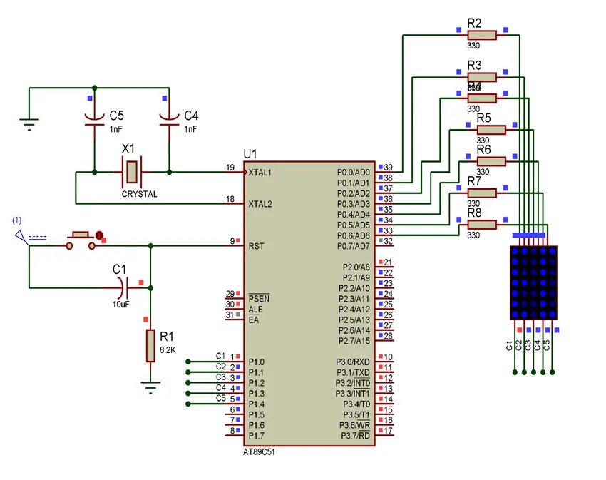
The circuit centers on a PIC 16F84A microcontroller. This chip runs at 4 MHz and has two I/O ports: Port A with 5 pins and Port B with 8 pins.
Port A controls which column is active. Each pin connects to one column of the LED matrix. Only one column turns on at a time. Port B controls which rows light up within the active column. The 7 data pins map to the 7 rows of LEDs.
The eighth pin of Port B serves as an input. A push button connects here, though the main program runs without user interaction.
Current limiting resistors sit between the microcontroller and the LEDs. Without them, the LEDs would draw too much current and damage either themselves or the chip.
The Assembly Code
The program starts by configuring the hardware. Port A and most of Port B become outputs. The timer gets set up with a prescaler of 64, which divides the clock to create usable timing intervals.
Interrupts drive the timing. The Timer0 module counts clock cycles. When it overflows, an interrupt fires. The interrupt handler decrements a counter. After 50 overflows, roughly half a second has passed, and the display advances to the next character.
The main loop handles the actual display. It reads the current character index and jumps to the appropriate letter routine. Each letter routine outputs the correct row patterns for each of its five columns, one at a time.
How Letters Are Stored
Each letter exists as a sequence of five column patterns. Take the letter “A” for example. The first column lights rows 1 through 6 except the middle. The next three columns light the top row and the middle row. The fifth column mirrors the first.
These patterns are stored as binary values that get written directly to Port B. A zero in a bit position means that LED turns on (active low). A one means it stays off. The pattern B'11000000' lights the bottom six LEDs of a column.
The code uses a table lookup approach. The character index feeds into a computed goto that jumps to the right letter routine. This avoids long chains of if-then checks.
Timing and Persistence of Vision
The display relies on scanning fast enough that the eye blends the columns together. Each column displays for just a brief moment before the code moves to the next.
The interrupt runs independently from the display loop. While the main loop cycles through columns, the timer counts in the background. When enough time passes, the interrupt increments the character pointer.
This separation keeps the display smooth. The column scanning never pauses to check the clock. The timing happens automatically through hardware interrupts.
Special Characters
Beyond the alphabet, the code includes a star pattern. Four asterisks appear at the end of each name, creating a visual separator before the sequence restarts.
The star uses a diamond shape: narrow at top and bottom, wide in the middle. The middle column has all LEDs lit. The adjacent columns have fewer. This creates a recognizable decorative element.
Challenges I Faced
Getting the timing right took experimentation. Too fast and the display looked dim because each LED had less time to shine. Too slow and the letters flickered noticeably.
The binary patterns for letters required careful planning. I mapped out each letter on graph paper first. One mistake in a bit pattern and the letter looked wrong or corrupted other characters.
Memory constraints forced efficiency. The PIC 16F84A has only 1K of program memory and 68 bytes of RAM. Every instruction counts. The letter patterns consume significant space, leaving little room for extra features.
Debugging assembly on hardware is hard. No print statements, no debugger. When something went wrong, I had to reason through the code instruction by instruction. A simulator helped, but it could not catch timing issues that only appeared on real hardware.
What I Learned
This project taught me how displays actually work at the hardware level. Every screen uses some form of scanning. Even modern monitors refresh pixel by pixel. The principles from this simple matrix apply everywhere.
Assembly programming forces you to understand the machine. No abstraction layers hide what the processor does. Every register, every clock cycle matters. This mindset proved valuable when I later worked with higher-level languages. Understanding what happens underneath helps you write better code at any level.
Hardware interrupts changed how I think about concurrent programming. The main loop and the timer run independently but share state through a counter variable. This is the simplest form of concurrency, but it demonstrates the same patterns that cause race conditions in complex systems.