Timing matters. Whether you are debugging a circuit or measuring reaction times, a stopwatch is a basic tool. In my Computer Architecture course, the assignment was simple: build a chronometer using a PIC microcontroller. No high-level languages. No libraries. Just raw assembly and a handful of hardware components.
The PIC 16F84A is a classic 8-bit microcontroller from Microchip. It has 1KB of program memory, 68 bytes of RAM, and runs at 4 MHz. These constraints force you to think about every instruction. You can not waste cycles or memory.
This project taught me how computers actually work at the lowest level. Registers, interrupts, timing loops. Things that high-level programming hides from you.
What It Does
The chronometer displays time on four 7-segment displays. Two digits for seconds (00-59) and two digits for centiseconds (00-99). A button starts and stops the timer. Another button resets it.
The display uses multiplexing. Only one digit lights up at a time, but switching between them fast enough creates the illusion of all four showing at once. This saves I/O pins. Instead of needing 28 pins for four displays, I use 12.
Timing comes from the microcontroller’s internal timer. An interrupt fires every 10 milliseconds to update the count. The main program loop handles the display refresh.
Hardware Design
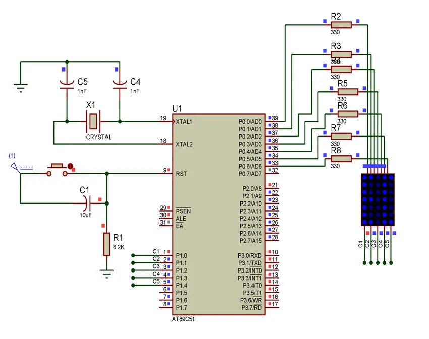
The circuit connects to the PIC through two ports:
Port B drives the 7-segment displays. Seven pins control which segments light up. The eighth pin reads the start/stop button.
Port A selects which digit is active. Four pins cycle through the four displays. The fifth pin reads the reset button.
Each display has a common cathode. When its control pin goes high, current flows through the lit segments. The pattern on Port B determines which segments glow.
The 7-segment encoding follows standard conventions. Each digit from 0 to 9 maps to a specific bit pattern. A lookup table in program memory holds these patterns.
Timer Interrupt
The PIC 16F84A has an 8-bit timer called TMR0. It counts clock cycles and triggers an interrupt when it overflows from 255 to 0.
With a 4 MHz crystal and a prescaler of 256, each timer tick is 256 microseconds. Loading the timer with 217 gives about 10 milliseconds between interrupts. This creates the 100 Hz timebase for centisecond counting.
The interrupt handler does the time arithmetic. It increments the centiseconds counter. When it reaches 10, it resets and increments the tens of centiseconds. Same pattern for seconds and tens of seconds. The tens of seconds counter wraps at 6 to keep the display under 60 seconds.
Display Multiplexing
The main loop cycles through all four digits rapidly. For each digit:
- Load the current time value for that position
- Look up the 7-segment pattern in the conversion table
- Output the pattern to Port B
- Enable that digit’s control line on Port A
- Wait a short delay
- Disable the control line
- Move to the next digit
The delay routine uses a simple countdown loop. Each iteration takes a known number of cycles. This gives consistent timing without using the hardware timer, which is already busy with the interrupt.
The Lookup Table
Converting a number to its 7-segment pattern uses a computed jump. The value serves as an offset into a table of return instructions. Each return instruction carries the segment pattern as immediate data.
The table handles digits 0 through 9. For example, the digit 8 lights all seven segments, while 1 only lights two. The patterns use active-low logic, where a 0 bit turns a segment on.
Button Handling
The start/stop button on Port B pin 7 controls the timer. When pressed (pin reads low), the program enables the timer interrupt and starts counting. When released (pin reads high), the program disables the interrupt and freezes the display.
The reset button on Port A pin 4 works differently. Pressing it clears the interrupt control register, stopping the count and returning to the wait state.
Button debouncing happens naturally through the display loop timing. The loop runs slow enough that switch bounce settles before the next check.
Memory Layout
The PIC 16F84A uses a Harvard architecture with separate program and data memory. Program memory starts at address 0. The interrupt vector sits at address 4.
The main code starts at address 80 (hexadecimal). This leaves room for the interrupt handler near the beginning. General-purpose registers hold the time values and temporary variables.
The entire program fits in about 95 words of program memory. That is less than 10% of the available space. Embedded systems often have more constraints, but this project stayed well within limits.
Challenges
Timing accuracy required careful calculation. The crystal frequency, prescaler, and timer load value all affect the interval. Getting exactly 10 milliseconds needed trial and error with the simulator.
Display brightness varied with refresh rate. Too slow and the digits flickered. Too fast and they were dim because each digit got less on-time. Finding the balance took experimentation.
Context switching in the interrupt handler needed attention. The handler saves the working register on entry and restores it on exit. Forgetting this corrupts the main program’s calculations.
Tools Used
MPASM assembled the source code into machine code. It produces a HEX file that programs into the chip.
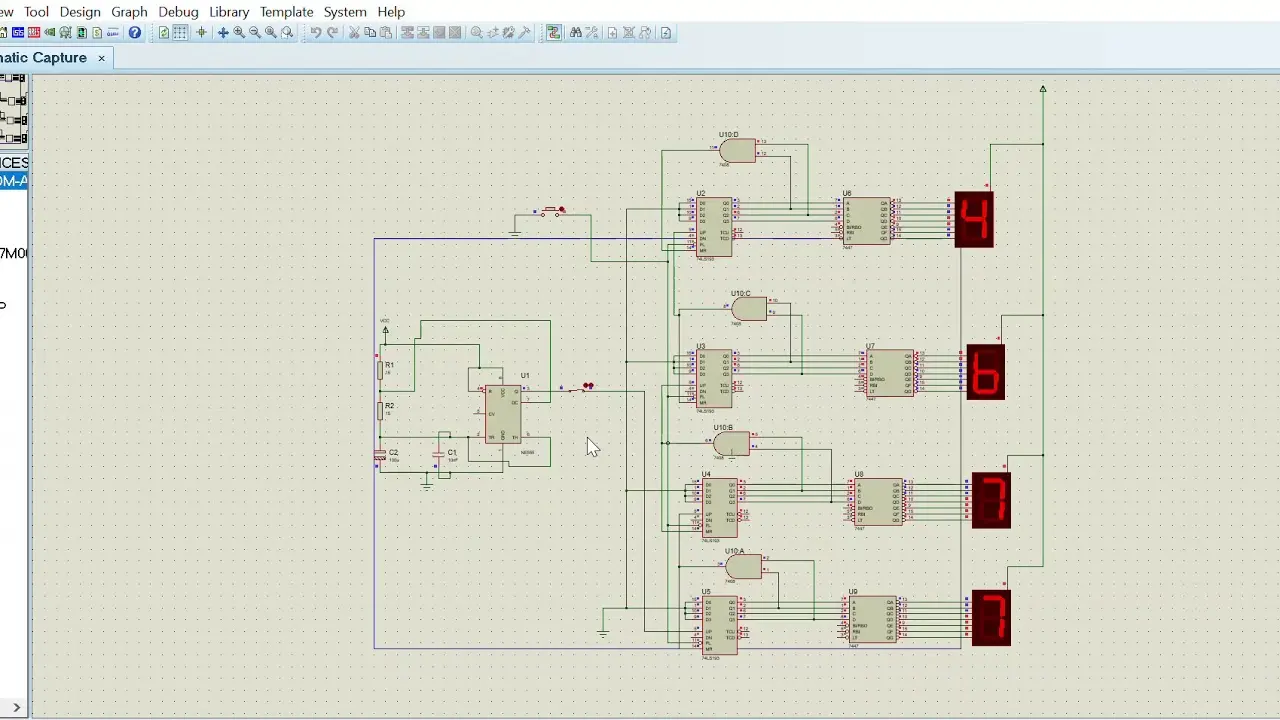
Proteus simulated the circuit before building hardware. I could run the code, watch the registers, and verify timing without burning chips.
The DSN file in the repository is the Proteus schematic. It includes the PIC, displays, buttons, and power supply.
What I Learned
Writing assembly forces you to understand the machine. Every instruction matters. You cannot hide behind abstractions.
Interrupt-driven programming changes how you structure code. The main loop and the interrupt handler run concurrently. Shared variables need careful management.
Hardware and software interact directly. A mistake in either domain breaks the system. Debugging requires thinking about both at once.
This project gave me an appreciation for what compilers do. Translating high-level logic into efficient machine code is hard. The patterns I learned here helped me write better code in every language since.